
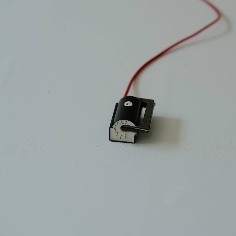
Core Design Parameters That Dictate the Need for a Custom Flyback Transformer
Turns Ratio, Winding Configuration, and Switching Frequency Alignment
Precise turns ratio calibration is essential for optimal voltage conversion and efficiency in flyback transformers. Standard units often force compromises—such as mismatched input/output voltages or suboptimal switching frequencies—that risk core saturation and inefficiency. Custom designs resolve this by aligning winding configurations with application-specific switching frequencies (typically 50–200 kHz), ensuring stable operation across the full load range. Interleaved windings reduce leakage inductance by 15–30% versus conventional layered layouts, directly lowering switching losses. When dynamic loads demand rapid response—like in servo controllers or battery chargers—custom synchronization between control ICs and transformer behavior prevents voltage overshoot while sustaining 90% efficiency from 20% to full load.
Core Material and Geometry Selection for Thermal and EMI Control
Ferrite core composition critically influences thermal performance and EMI behavior. Off-the-shelf transformers commonly use generic MnZn ferrites with narrow operating temperature windows, exhibiting measurable degradation above 85°C. Custom solutions select core geometry (E-core, toroidal, or planar) and material grade based on thermal dissipation needs—reducing hotspot temperatures by 20–40°C in space-constrained layouts. Nanocrystalline alloys cut high-frequency core losses by up to 45% while offering intrinsic EMI shielding. Strategic gapping further suppresses common-mode noise, enabling compliance with FCC Part 15 emissions limits without external filtering.
| Design Factor | Standard Transformer Impact | Custom Solution Benefit |
|---|---|---|
| Core Material | Generic ferrite (≤100°C) | Nanocrystalline (150°C+) |
| Thermal Rise | 15–20% derating at full load | <5% efficiency drop at peak load |
| EMI Signature | Requires additional filters | Intrinsic 40 dB noise reduction |
Performance Realities: Efficiency, Reliability, and Cost Implications of Each Approach
How Custom Flyback Transformer Winding Optimization Improves Efficiency Under Dynamic Loads
Custom flyback transformers deliver up to 12% higher efficiency under variable-load conditions compared to standard models. This gain stems from targeted reductions in core loss, copper loss, and leakage inductance—achieved through precision turns ratios, interleaved winding patterns, and optimized conductor sizing. As documented in IEEE Transactions on Power Electronics (2023), such optimization cuts leakage inductance by ~40%, significantly lowering switching losses. The result is sustained 92% efficiency across 20–100% load ranges—a key advantage for applications like variable-speed motor drives and medical power supplies. Although custom units carry a 15–30% premium, energy savings typically offset the added cost within 18 months for systems operating at ≥60% utilization.
Reliability Risks of Derating Standard Flyback Transformers in Harsh Operating Conditions
Derating standard flyback transformers in demanding environments introduces measurable reliability penalties. At 85°C ambient, derated cores exhibit triple the failure rate of thermally robust custom alternatives (Electronics Cooling Journal, 2023). Humidity exposure above 60% RH accelerates insulation degradation by 25%. Custom designs counter these risks with purpose-built thermal management—including geometry-optimized cores, IEC 62368-1–compliant isolation materials, and potting compounds engineered for thermal cycling resilience. In industrial deployments, these enhancements reduce MTBF variance by 70%, delivering predictable lifetime performance where field failures are costly or safety-critical.
Regulatory and Safety Requirements That Necessitate Custom Flyback Transformer Design
Meeting IEC 62368-1 Creepage, Clearance, and Insulation Requirements
IEC 62368-1 mandates strict minimum distances for creepage (along surfaces), clearance (through air), and insulation integrity—especially in high-voltage or humid environments. Standard flyback transformers rarely meet these thresholds out of the box: their fixed bobbin geometries and single-layer insulation often fall short of the 8 mm+ creepage required for reinforced insulation above 300 VAC. Custom implementations address this with wider conductor spacing, triple-insulated wire, and reinforced dielectric bobbins. These features prevent dielectric breakdown—the leading cause of catastrophic transformer failure in safety-critical systems. Third-party certification also requires validated thermal margins at elevated altitudes (2000 m) or ambient temperatures (70°C)—conditions standard units cannot reliably satisfy without sacrificing efficiency or safety margin.
When Standard Flyback Transformers Are the Optimal Choice
Standard flyback transformers remain the pragmatic, high-value choice when application requirements align closely with commercial specifications. For power levels under 150 W—common in USB-C adapters, phone chargers, LED drivers, and industrial I/O modules—they offer proven reliability, rapid time-to-market, and no custom development overhead. Their inherent simplicity supports multiple isolated outputs from a single magnetic component, eliminating the need for auxiliary inductors. This makes them especially cost-effective in medium-power applications where thermal stress, regulatory complexity, or extreme load dynamics are absent.
For output currents below 10 A and stable load profiles, standard units balance performance and economics—particularly when high-output voltages are needed but transient response demands are modest. In controlled environments (e.g., indoor, 0–50°C ambient, sea-level operation), their well-characterized behavior avoids core saturation risks and satisfies IEC 62368-1 with minimal design effort. With immediate availability and no 4–8 week lead times, they let manufacturers accelerate validation and reduce supply-chain risk—making them the optimal solution for non-specialized, volume-driven applications.
FAQ
What are the advantages of custom flyback transformers?
Custom flyback transformers provide precise turns ratio calibration and optimized winding configurations to prevent core saturation, inefficiency, and voltage overshoot. They align with specific switching frequencies and reduce leakage inductance and switching losses, resulting in higher efficiency and stability across various loads.
Why is core material selection important in transformer design?
The core material significantly impacts a transformer's thermal performance and electromagnetic interference (EMI). Choosing the right material, such as nanocrystalline alloys, can reduce core losses, offer EMI shielding, and improve thermal control, especially in space-constrained or demanding applications.
How do custom transformers meet regulatory and safety requirements?
Custom transformers are designed to meet stringent regulatory and safety standards, such as IEC 62368-1, by ensuring compliance with creepage, clearance, and insulation requirements. They employ features like wider conductor spacing and reinforced dielectric bobbins to prevent dielectric breakdown and ensure reliable operation.
When should standard flyback transformers be considered as an option?
Standard flyback transformers are suitable when application requirements align with commercial specifications and regulatory standards. They are ideal for applications under 150 W, offering quick time-to-market, cost-effectiveness, and reliability in controlled environments that demand stable output profiles.
Table of Contents
- Core Design Parameters That Dictate the Need for a Custom Flyback Transformer
- Performance Realities: Efficiency, Reliability, and Cost Implications of Each Approach
- Regulatory and Safety Requirements That Necessitate Custom Flyback Transformer Design
- When Standard Flyback Transformers Are the Optimal Choice
- FAQ