
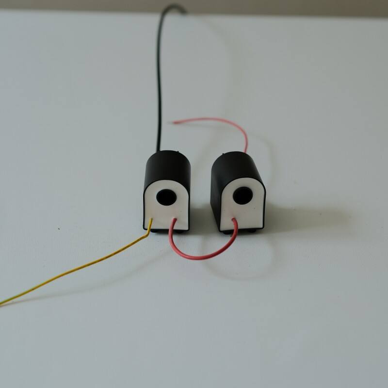
Insulation Integrity Testing Under High-Frequency Flyback Stress
Dielectric Withstand and Partial Discharge Testing per VDE 0806 & IEC 61558
Dielectric withstand testing applies high-potential AC/DC voltages to verify insulation breakdown thresholds in flyback transformers, with VDE 0806 specifying 3 kV RMS for 60 seconds. Complementing this, partial discharge (PD) detection identifies micro-discharges below breakdown levels—critical in high-frequency operation where switching transients accelerate insulation fatigue. Per IEC 61558, PD must remain below 10 pC when tested at 1.5× operating voltage; phase-resolved pulse analysis enables precise localization of weaknesses in inter-winding barriers or magnet wire coatings. Modern test systems use variable-frequency sources (20–200 kHz) to replicate real flyback conditions, revealing frequency-dependent failure modes—such as corona inception at resonant points—that fixed-frequency tests miss.
Thermal-Ageing Accelerated Insulation Degradation Analysis
Thermal-accelerated life testing subjects insulation systems to elevated temperatures (130–180°C) while tracking dielectric strength decay. This follows the Arrhenius model: each 10°C rise approximately doubles chemical degradation velocity. Standardized thermal cycling—e.g., 500 hours at 150°C followed by dielectric validation—exposes embrittlement in polymer films and varnishes. Concurrent insulation resistance monitoring detects progressive leakage current growth; a 40% resistance drop signals end-of-life. These protocols compress 15-year field lifetime predictions into just eight weeks, enabling early material qualification before production deployment.
Precision Leakage Inductance Measurement for Flyback Transformer Performance
Accurate leakage inductance quantification directly governs flyback efficiency and voltage regulation—measurement variances alone can cause ±15% performance deviations in SMPS designs.
LCR Meter Frequency Sweep vs. Fixed-Frequency Bias: Best Practices for Flyback Transformer Characterization
Frequency sweeps (1 kHz–1 MHz) capture nonlinear inductance behavior under actual operating conditions, unlike fixed-frequency measurements that obscure core saturation effects. Sweeping reveals resonant interactions between leakage inductance and interwinding capacitance—especially critical for flyback transformers switching at 65–200 kHz. Fixed-bias methods risk underreporting inductance drift by up to 22% during load transients and should be avoided when validating high-ΔB designs.
Short-Circuit Impedance Method for Accurate Leakage Inductance Extraction
The shorted-secondary method isolates leakage inductance (Llk) by measuring primary impedance while neutralizing mutual flux. Best practices include:
- Using vector network analyzers for phase-sensitive, wideband impedance capture
- Limiting test current to <5% of rated value to avoid core saturation influence
- Compensating for winding ESR via Q-factor-derived correction
- Validating results using Faraday-shielded comparative tests
This approach achieves ±3% reproducibility for sub-5 μH values—more than three times tighter than the ±9% typical of three-terminal techniques.
Resolving Measurement Conflicts: Parasitics, Core Effects, and Real-World Flyback Transformer Behavior
How Interwinding Capacitance and Dynamic Core Saturation Distort Leakage Inductance Readings
Interwinding capacitance and dynamic core saturation jointly distort leakage inductance measurements. Parasitic capacitance forms resonant circuits that absorb energy during LCR sweeps—artificially inflating readings by up to 30% above 100 kHz. Simultaneously, core saturation under operating flux reduces effective permeability, causing inductance to drop by as much as 40% versus small-signal values. Together, these effects mean fixed-frequency tests often overstate operational leakage inductance by 15–25%. Reliable characterization therefore requires frequency-domain analysis combined with controlled bias-current simulation to decouple parasitic and magnetic influences.
Why Lower Leakage Inductance ≠ Better Flyback Efficiency: A Design Context Perspective
Minimizing leakage inductance does not universally improve flyback efficiency. Over-reduction raises di/dt, generating voltage spikes exceeding twice the input voltage—necessitating larger snubber networks whose losses can outweigh switching gains, especially in discontinuous conduction mode (DCM). Conversely, moderate leakage inductance (5–8% of magnetizing inductance) enables zero-voltage switching (ZVS) in resonant variants, cutting turn-on losses by up to 35%. Optimal leakage is thus system-dependent: shaped by operating frequency, core material, output power, and topology—not by absolute minimization.
FAQ
What is dielectric withstand testing in flyback transformers?
Dielectric withstand testing involves applying high-potential AC/DC voltages to check for insulation breakdown in flyback transformers, ensuring they can tolerate the stress levels they will face in operation.
Why is partial discharge detection critical for high-frequency operations?
Partial discharge detection identifies micro-discharges before actual breakdown occurs, which is crucial in high-frequency applications where switching transients can accelerate insulation fatigue.
How does thermal-accelerated life testing work?
It subjects insulation systems to high temperatures, accelerating their degradation to predict their lifespan within a fraction of the time it would take under normal conditions.
Why is accurate leakage inductance measurement important for flyback transformers?
Accurate leakage inductance measurement is vital for ensuring efficient flyback transformer performance and proper voltage regulation.
What are the best practices for measuring leakage inductance in flyback transformers?
Using frequency sweeps for non-linear inductance behavior capture and short-circuit impedance methods for accurate leakage inductance extraction are recommended practices.