High Voltage Flyback Transformer Circuit: Efficient Power Conversion Solutions for Demanding Applications

Get a Free Quote

Our representative will contact you soon.
Email
Mobile/WhatsApp
Name
Company Name
Message
0/1000

high voltage flyback transformer circuit

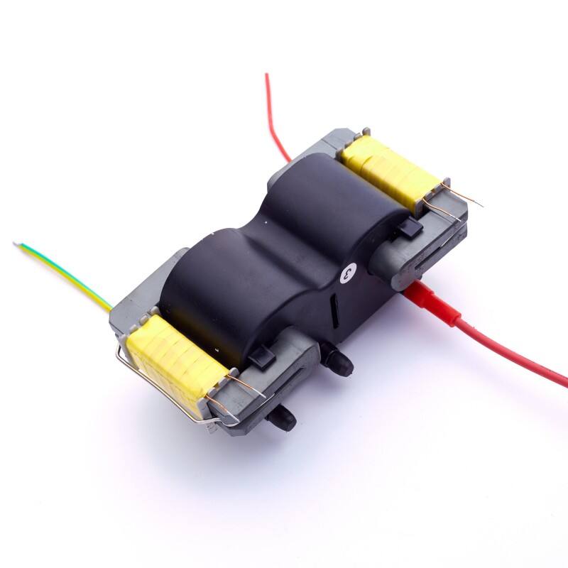
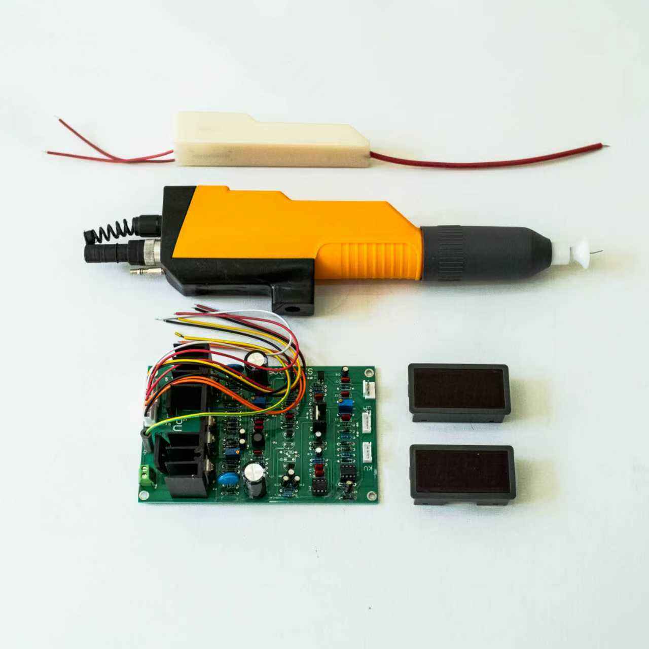
The high voltage flyback transformer circuit represents a fundamental power conversion topology widely utilized in electronics where substantial voltage step-up capabilities are required. This circuit configuration derives its name from the flyback operation principle, where energy storage and transfer occur during distinct phases of the switching cycle. At its core, the high voltage flyback transformer circuit consists of a switching transistor, a specially designed transformer with primary and secondary windings, rectification diodes, filtering capacitors, and control circuitry that orchestrates the entire operation. The primary function involves converting low input voltages into significantly higher output voltages, often reaching several thousand volts, making it indispensable for applications demanding elevated potential differences. The technological foundation rests upon electromagnetic induction principles combined with precise switching control mechanisms. During the on-state of the switching transistor, electrical current flows through the primary winding, storing magnetic energy within the transformer core. When the transistor switches off, this stored energy rapidly transfers to the secondary winding, inducing a voltage proportional to the turns ratio between windings. The flyback configuration uniquely allows the transformer to function simultaneously as an energy storage inductor and a voltage transformation device. This dual functionality distinguishes it from conventional forward-mode transformers. Applications span diverse industries including cathode ray tube displays, medical imaging equipment, industrial power supplies, plasma generation systems, electrostatic precipitation units, and scientific instrumentation requiring stable high voltage sources. The circuit's versatility enables designers to achieve multiple isolated outputs with different voltage levels from a single transformer, enhancing system integration and reducing component count. Modern implementations incorporate advanced control strategies such as pulse width modulation, frequency modulation, and resonant switching techniques to optimize efficiency and minimize electromagnetic interference. The high voltage flyback transformer circuit continues evolving with semiconductor advancements, enabling higher switching frequencies, improved power density, and enhanced reliability for contemporary electronic systems demanding compact, efficient, and precise high voltage generation capabilities across commercial, industrial, and specialized application domains.

New Product Recommendations

The high voltage flyback transformer circuit offers numerous practical benefits that directly impact performance, cost-effectiveness, and design flexibility for your applications. First and foremost, this circuit provides exceptional voltage multiplication capabilities within a compact footprint. Unlike complex voltage multiplier cascades requiring numerous discrete components, the high voltage flyback transformer circuit achieves dramatic voltage increases through a single transformer component combined with minimal supporting circuitry. This simplification translates to reduced board space, lower assembly costs, and improved system reliability through fewer potential failure points. The design inherently supports electrical isolation between input and output stages, providing crucial safety advantages in applications where users or sensitive equipment must remain protected from high voltage sections. This galvanic isolation eliminates ground loop problems and permits flexible system grounding configurations without compromising operational safety. Another significant advantage centers on the circuit's ability to regulate output voltage efficiently across varying load conditions. By adjusting the switching duty cycle or frequency, the high voltage flyback transformer circuit maintains stable output voltage despite input fluctuations or changing power demands. This built-in regulation capability reduces or eliminates the need for additional voltage regulation stages, streamlining overall system architecture. Cost efficiency emerges as a compelling benefit, particularly for moderate power applications. The transformer design allows manufacturers to optimize core materials, winding configurations, and insulation systems specifically for flyback operation, resulting in economical component pricing compared to alternative high voltage generation methods. Energy efficiency represents another practical advantage, with modern high voltage flyback transformer circuits achieving conversion efficiencies exceeding eighty-five percent in well-designed implementations. This efficiency reduces heat generation, lowers cooling requirements, and decreases operational expenses over the product lifetime. The topology naturally accommodates multiple output voltages from a single transformer, enabling designers to power various subsystems with different voltage requirements without duplicating conversion stages. This multi-output capability proves especially valuable in complex systems requiring both high voltage supplies and auxiliary lower voltage rails. Implementation flexibility allows engineers to optimize the high voltage flyback transformer circuit for specific priorities whether maximizing efficiency, minimizing electromagnetic emissions, reducing component stress, or achieving particular dynamic response characteristics. The circuit readily adapts to different control strategies and feedback mechanisms, supporting both simple and sophisticated regulation approaches depending on application requirements. Manufacturing and testing processes benefit from the circuit's straightforward topology, facilitating quality control and reducing production complexity. Troubleshooting becomes more manageable due to the limited component count and well-understood operational principles. For applications requiring portability or battery operation, the high voltage flyback transformer circuit delivers excellent performance from low voltage DC sources, making it ideal for handheld instruments, portable medical devices, and field equipment. The absence of bulky line-frequency transformers and the ability to operate at elevated switching frequencies enable lightweight, portable designs previously unattainable with conventional approaches.

Latest News

Predictive Maintenance: Using IoT Sensors to Monitor High Voltage Module Health

19

May

Predictive Maintenance: Using IoT Sensors to Monitor High Voltage Module Health

Why High Voltage Modules Demand Predictive—Not Preventive—Maintenance High voltage modules face unique failure risks—insulation degradation, partial discharge, and thermal runaway—where traditional preventive maintenance con...
View More
Nozzle Geometry and Spray Patterns: Matching Gun Design to Part Complexity

16

Jun

Nozzle Geometry and Spray Patterns: Matching Gun Design to Part Complexity

How Nozzle Geometry Shapes Spray Pattern Formation in Powder Coating Spray Guns Swirl Chamber Design and Inlet Orientation: Axial vs. Tangential Flow Effects on Pattern Symmetry Swirl chamber configuration fundamentally governs airflow dynamics&mda...
View More
How does a flyback transformer contribute to energy saving and efficiency

08

Apr

How does a flyback transformer contribute to energy saving and efficiency

In modern power electronics, the demand for energy-efficient solutions has never been more critical. Industries worldwide are seeking components that not only deliver reliable performance but also minimize energy waste and operational costs. The flyb...
View More
How Does a Powder Coating Spray Gun Improve Coating Quality

01

Apr

How Does a Powder Coating Spray Gun Improve Coating Quality

Achieving superior coating quality in industrial finishing operations depends heavily on the equipment used to apply the coating material. The powder coating spray gun has emerged as a critical tool in modern manufacturing environments where uniformi...
View More

Get a Free Quote

Our representative will contact you soon.
Email
Mobile/WhatsApp
Name
Company Name
Message
0/1000

high voltage flyback transformer circuit

Superior Energy Efficiency and Thermal Performance

Superior Energy Efficiency and Thermal Performance

The high voltage flyback transformer circuit demonstrates remarkable energy efficiency characteristics that directly benefit operational costs, system longevity, and environmental sustainability. Modern implementations of this topology routinely achieve conversion efficiencies between eighty and ninety percent, meaning the vast majority of input power successfully converts to useful output power rather than dissipating as waste heat. This efficiency advantage stems from several inherent design features working synergistically. The switching operation minimizes resistive losses by maintaining the power transistor in either fully-on or fully-off states, avoiding the linear region where simultaneous high voltage and current conditions create substantial power dissipation. Advanced semiconductor devices such as MOSFETs and IGBTs exhibit extremely low on-resistance values, further reducing conduction losses during current flow periods. The transformer itself contributes to overall efficiency through careful magnetic core selection and winding optimization. Engineers specify core materials with low hysteresis and eddy current losses at the chosen operating frequency, ensuring minimal energy waste during each magnetic reversal cycle. Copper windings sized appropriately for current-carrying requirements maintain low resistive losses while proper interwinding capacitance management reduces circulating currents that would otherwise decrease efficiency. The high voltage flyback transformer circuit's ability to operate at elevated switching frequencies, typically ranging from twenty kilohertz to several hundred kilohertz, enables the use of smaller magnetic components with reduced core losses compared to line-frequency alternatives. This frequency advantage allows designers to select optimized core geometries that minimize magnetic path length and maximize coupling between primary and secondary windings. Thermal performance directly correlates with efficiency levels, as higher efficiency means less heat generation requiring dissipation. Reduced thermal stress extends component lifespan, decreases cooling system requirements, and improves overall reliability. In battery-powered applications, superior efficiency translates to extended operating duration per charge cycle, enhancing user experience and reducing recharging frequency. For grid-powered systems, improved efficiency lowers electricity consumption, reducing operational expenses and environmental impact. The high voltage flyback transformer circuit achieves these efficiency benefits while maintaining excellent voltage regulation and transient response characteristics. Sophisticated control algorithms monitor output conditions and dynamically adjust switching parameters to optimize efficiency across varying load levels. Some implementations employ resonant or quasi-resonant switching techniques that further enhance efficiency by recovering energy otherwise lost during switching transitions. These advanced approaches enable zero-voltage or zero-current switching conditions that dramatically reduce switching losses, pushing overall efficiency toward theoretical maximum values.
Exceptional Design Flexibility and Multi-Output Capability

Exceptional Design Flexibility and Multi-Output Capability

One of the most compelling attributes of the high voltage flyback transformer circuit lies in its extraordinary design flexibility, enabling engineers to tailor implementations precisely to specific application requirements while supporting multiple voltage outputs from a single conversion stage. This adaptability proves invaluable across diverse industries where standardized solutions fall short of meeting unique technical demands. The transformer component itself offers tremendous customization potential, with turns ratio selection determining the fundamental voltage conversion relationship between primary and secondary sides. Designers specify this ratio to achieve desired output voltage levels while balancing factors such as component stress, switching frequency, and efficiency optimization. Unlike fixed-ratio solutions, the high voltage flyback transformer circuit accommodates virtually any practical voltage multiplication factor through appropriate transformer design. Multiple secondary windings can be incorporated within a single transformer structure, each providing a different output voltage level with independent rectification and filtering. This multi-output capability eliminates the need for separate conversion stages, reducing component count, board space, and system cost while improving overall reliability through simplified architecture. Each output maintains electrical isolation from others and from the input, providing flexibility in grounding configurations and preventing interaction between different voltage domains. The high voltage flyback transformer circuit readily adapts to various control strategies depending on performance priorities. Simple voltage-mode control offers straightforward implementation with minimal component count, suitable for cost-sensitive applications with moderate performance requirements. Current-mode control provides superior transient response and inherent cycle-by-cycle current limiting, protecting components from overcurrent conditions while improving dynamic regulation. Peak current control, average current control, and boundary conduction mode operation each offer distinct advantages that designers can leverage based on specific application needs. Frequency modulation techniques allow the high voltage flyback transformer circuit to maintain regulation by varying switching frequency rather than duty cycle, beneficial in applications where constant frequency operation creates electromagnetic interference challenges. Burst mode operation enables extremely high efficiency at light loads by delivering energy in periodic bursts rather than continuous switching, ideal for standby power applications where minimizing consumption during idle periods is paramount. The topology accommodates both continuous and discontinuous conduction modes, each offering particular benefits. Continuous mode operation typically provides lower current ripple and reduced electromagnetic emissions, while discontinuous mode simplifies control implementation and naturally provides output diode turn-off at zero current, eliminating reverse recovery losses. Designers select the optimal operating mode based on power level, switching frequency, and efficiency targets. Input voltage range flexibility represents another significant advantage, with the high voltage flyback transformer circuit successfully operating across wide input voltage variations through appropriate control loop design. This capability proves especially valuable in battery-powered applications where input voltage decreases as discharge progresses, or in universal input applications accommodating different regional power standards.
Enhanced Safety Features and Robust Isolation Protection

Enhanced Safety Features and Robust Isolation Protection

Safety considerations occupy paramount importance in high voltage applications, and the high voltage flyback transformer circuit incorporates inherent protective features that safeguard both users and connected equipment from electrical hazards. The fundamental topology provides galvanic isolation between input and output circuits through the magnetic coupling of the transformer, creating a physical barrier without direct electrical connection. This isolation prevents fault conditions on one side from propagating to the other, protecting sensitive low-voltage control circuitry and input power sources from high voltage transients or failures. Regulatory standards governing electrical safety mandate specific isolation requirements measured in voltage withstand capability and creepage distances, and the high voltage flyback transformer circuit readily satisfies these requirements through proper transformer construction techniques. Manufacturers incorporate multiple insulation layers, barrier tape materials, and physical separation between primary and secondary windings to achieve isolation ratings often exceeding several thousand volts. This robust isolation proves essential in medical equipment, industrial instrumentation, and consumer electronics where user safety cannot be compromised under any foreseeable fault condition. The circuit naturally incorporates current-limiting behavior that provides inherent protection against short circuits and overload conditions. When output demand exceeds design limits, the transformer's leakage inductance and control system response combine to restrict current flow, preventing catastrophic component failure. Many implementations include explicit overcurrent protection mechanisms that monitor primary or secondary current levels and initiate shutdown sequences when thresholds are exceeded. These protection features operate rapidly, typically within microseconds, limiting energy delivery during fault conditions and preventing thermal damage to semiconductors, transformer windings, or other components. Overvoltage protection represents another critical safety aspect addressed effectively by the high voltage flyback transformer circuit. Feedback control loops continuously monitor output voltage and adjust switching parameters to maintain regulation within specified limits. Should the feedback path fail or become disrupted, backup protection circuits detect abnormal voltage levels and disable switching operation, preventing uncontrolled voltage escalation that could damage connected equipment or create shock hazards. The magnetic components themselves contribute to safety through saturation limiting behavior. If control circuitry malfunctions and attempts to deliver excessive energy, the transformer core enters magnetic saturation, dramatically reducing inductance and limiting further energy accumulation. This passive protection mechanism operates without requiring active monitoring circuits, providing fail-safe behavior even under catastrophic control failure scenarios. Thermal protection features commonly integrated within high voltage flyback transformer circuit implementations monitor component temperatures and initiate protective responses when safe operating limits approach. Temperature sensors attached to heat sinks, transformer cores, or semiconductor devices provide early warning of abnormal thermal conditions, allowing controlled shutdown before damage occurs. Arc and flashover prevention receives careful attention in high voltage flyback transformer circuit design through proper component spacing, conformal coating application, and potting compound encapsulation. These techniques prevent voltage breakdown through air or across insulating surfaces, maintaining safe operation even in challenging environmental conditions involving humidity, contamination, or altitude variations affecting dielectric strength.

Get a Free Quote

Our representative will contact you soon.
Email
Mobile/WhatsApp
Name
Company Name
Message
0/1000
Newsletter
Please Leave A Message With Us