
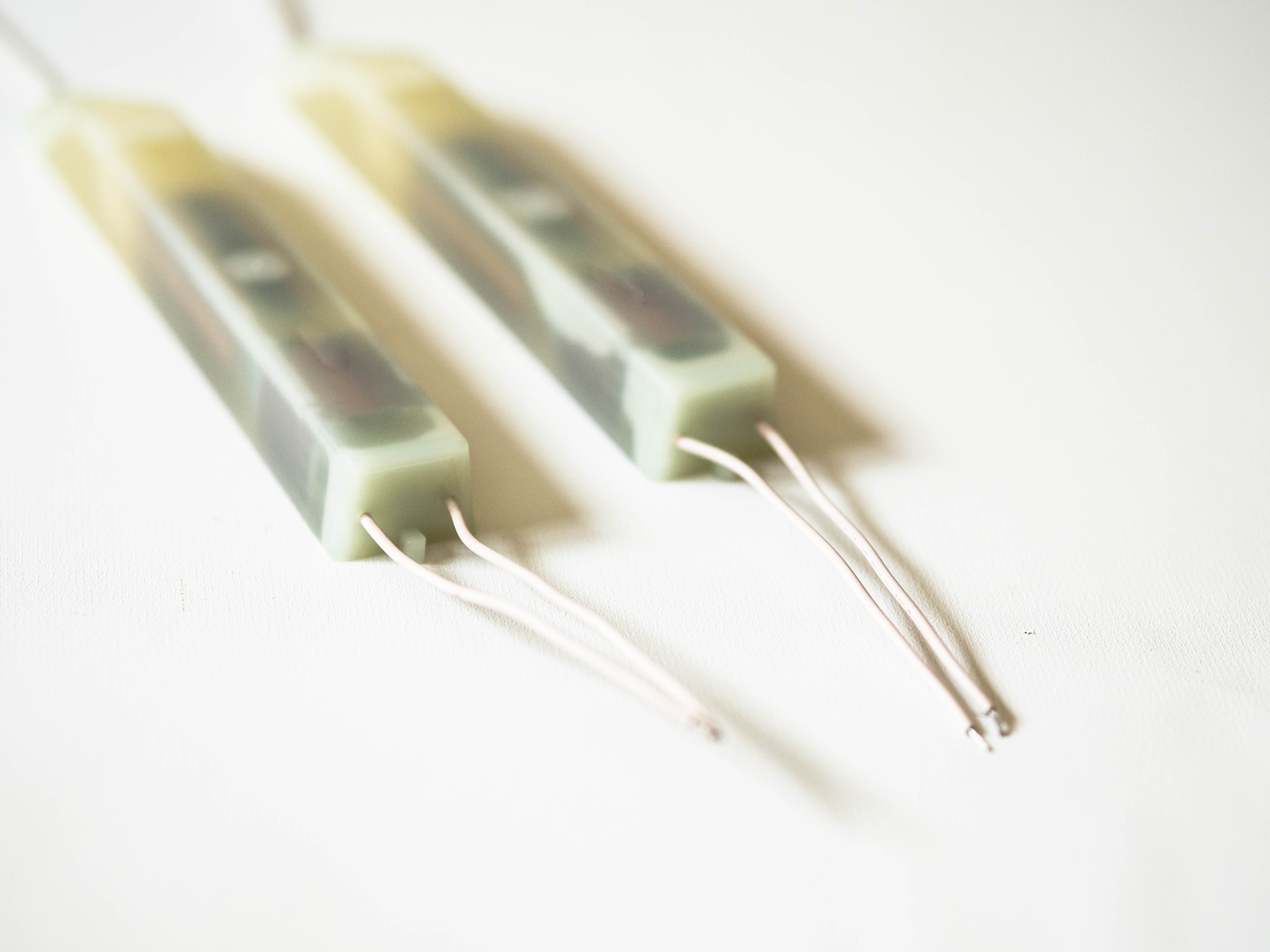
Selecting a flyback transformer model starts with the converter’s actual operating requirements, not a part number or a single headline rating. Define the input voltage range, required outputs, load behavior, switching frequency, and safety constraints first. Those conditions determine which flyback transformer characteristics matter and help prevent a design that meets a nominal specification but fails in operation.
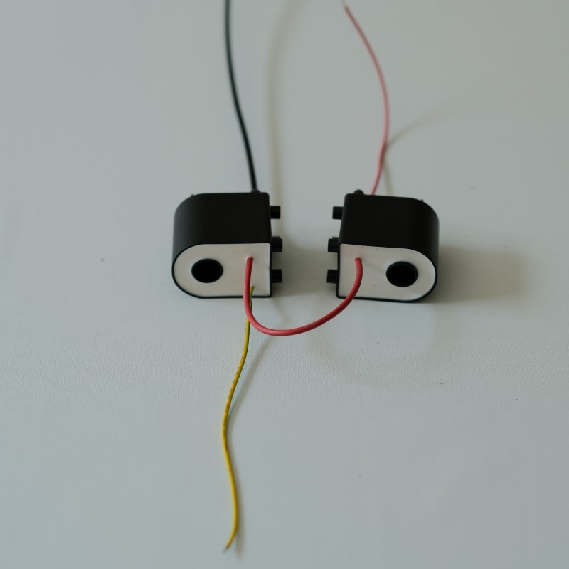
A reliable selection process links electrical, thermal, mechanical, and compliance requirements. Treat the flyback transformer as part of the complete power stage: its winding ratios, magnetizing inductance, insulation, and construction interact with the controller and surrounding circuit. The steps below turn a broad specification into a practical shortlist and identify what to verify before design approval.
Define the operating requirements first
Translate input and output needs
Record the minimum, nominal, and maximum input voltage, including expected transients. For each output, specify voltage, continuous current, peak demand, regulation tolerance, and whether the load can change abruptly. A flyback transformer must support the intended energy transfer across these conditions, so selecting it from output watts alone can overlook a demanding low-line or startup case.
Clarify whether the design uses one output or several, and identify which rail has the tightest regulation requirement. Winding arrangement and cross-regulation can affect how secondary voltages behave as loads shift. When comparing a flyback transformer against a preliminary design, check each rail at realistic simultaneous loading rather than assuming all outputs remain ideal when only one load is active.
Establish the electrical operating envelope
Next, confirm the controller topology, switching frequency range, duty-cycle limits, and primary current limit. These values shape peak current, flux excursion, and the energy a flyback transformer transfers per cycle. Include startup, overload, short-circuit, and light-load modes where relevant, because operating modes can place different demands on the magnetic component than steady-state full-load operation.
Estimate the required magnetizing inductance and turns ratio from the converter design, then check those values against the available design options. Leakage inductance also matters because it influences voltage spikes and clamp or snubber losses. A suitable flyback transformer specification should state tolerances for these parameters, not only nominal values, so the circuit can be assessed across production variation.
Match magnetic and insulation specifications
Check winding design and magnetic limits
Review primary and secondary turns, winding polarity, wire size, and any auxiliary winding needed for controller bias or sensing. A flyback transformer with the correct ratio may still be unsuitable if its winding resistance creates excessive copper loss or its layout produces unwanted coupling. Ask for drawings or a clear pinout so circuit connections and polarity can be checked before layout.
Assess core material and size in relation to frequency, power, temperature, and the allowable physical envelope. The flyback transformer must operate without unacceptable saturation or core loss at the worst-case input and load. Validate peak flux density using the intended waveform and tolerance assumptions; a simple power rating cannot substitute for checking the actual converter’s magnetic stress.
Specify isolation and environmental conditions
For isolated supplies, define the required working voltage, insulation class, creepage and clearance needs, and applicable dielectric test conditions. The flyback transformer construction must support the product’s end-use safety requirements, which depend on the system and governing standards. Confirm how margins, barriers, bobbin geometry, and winding techniques are represented in the documentation.
Temperature limits should reflect the enclosure, nearby heat sources, airflow, and duty cycle rather than room ambient alone. Check the flyback transformer’s specified operating and storage ranges, and consider humidity, vibration, and contamination where the application demands it. Material choices and insulation details should be reviewed against the real environment before the mechanical design is frozen.
Verify fit, performance, and production readiness
Confirm physical and circuit compatibility
Compare the package dimensions, mounting method, pin spacing, and board footprint with the available space and assembly process. A flyback transformer can satisfy electrical targets yet create a layout problem through pin placement, height, or required isolation spacing. Check access for inspection and confirm that its location will not compromise thermal paths or sensitive signal routing.
Use circuit simulations as an early screening tool, then evaluate a physical sample in the intended converter. Measure regulation, efficiency, temperature rise, startup behavior, and switching waveforms over the expected input and load range. This is where a flyback transformer specification can be compared with observed behavior rather than accepted solely from a datasheet.
Plan validation and document the final choice
Build a verification plan around the risks identified in the design: electrical stress, insulation integrity, thermal margin, noise, and abnormal operating conditions. Test the flyback transformer in the complete power stage, since controller settings, clamp design, PCB parasitics, and load dynamics affect results. Record test conditions so later design changes can be assessed consistently.
Before release, confirm the drawing revision, critical dimensions, electrical tolerances, materials, and agreed inspection criteria. Document why the selected flyback transformer meets the application envelope and which limits remain important during production. If requirements change, revisit the calculations and tests instead of assuming the original selection remains valid across a new input, load, or enclosure condition.
FAQ
Which specification should be checked first?
Start with the input range and required output loads, then relate them to switching conditions, current limits, and isolation needs. Those requirements establish the envelope for choosing a flyback transformer and reveal which detailed parameters need tighter control.
Can a transformer with the right power rating be used?
Not necessarily. Power rating alone does not confirm turns ratio, inductance, leakage, insulation, temperature capability, or physical fit. Check the complete flyback transformer specification against the converter and verify performance in the assembled circuit.
When should sample testing take place?
Test samples after the electrical design and layout are representative, and before production release. Evaluate worst-case operating conditions and safety requirements, then document results. This confirms that the flyback transformer works as intended within the actual system rather than only on paper.