

A flyback transformer can support energy-efficient power conversion by storing energy during one part of a switching cycle and delivering it during another. This operating method helps a compact supply provide isolated output voltage without a separate output inductor. However, a flyback transformer does not save energy automatically: its benefit depends on the circuit, operating conditions, and design quality.
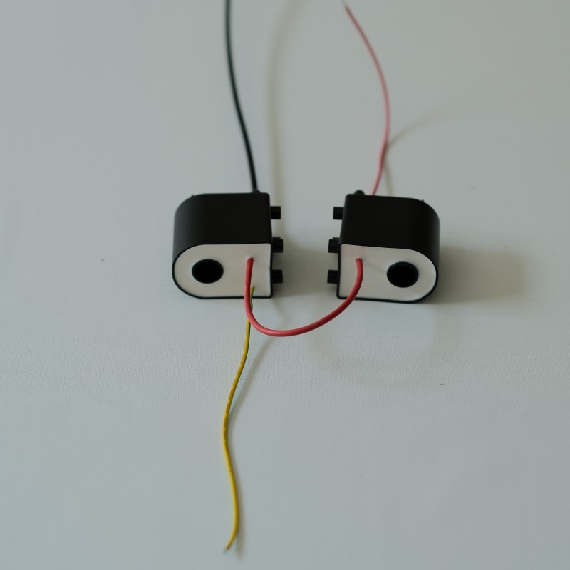
Understanding how a flyback transformer affects losses helps engineers choose a suitable topology and set realistic performance goals. The key is to follow energy through the switching cycle, then examine where it is stored, transferred, and dissipated. With that view, a flyback transformer can be evaluated as part of the complete power supply rather than as an isolated component.
How flyback energy transfer works
Energy storage across the switching cycle
A flyback transformer works more like a coupled inductor than a conventional transformer that transfers power continuously. When the primary switch turns on, current builds in the primary winding and energy is stored in the magnetic field. During this interval, the secondary rectifier is generally off. A flyback transformer therefore separates energy storage from delivery in time, allowing the control circuit to regulate output by adjusting switching behavior.
When the switch turns off, winding polarity changes and the secondary path conducts, sending stored energy to the output. This sequence lets a flyback transformer provide isolation and step-up or step-down conversion through winding ratios and circuit conditions. Because power moves in pulses, the output capacitor smooths the delivered energy. Correct timing and component selection help the flyback transformer perform this transfer without avoidable stress or excess loss.
Why the topology can use fewer parts
In many low- to moderate-power isolated supplies, a flyback transformer combines magnetic energy storage and voltage conversion in one magnetic component. The design may avoid a separate output inductor, reducing component count and potentially simplifying assembly. Fewer parts can also mean fewer sources of parasitic loss, although the complete design still needs rectification, switching, control, and filtering. A flyback transformer is useful when the system benefits from that integration.
The practical value depends on the target output, load range, isolation needs, and allowable size. A flyback transformer can supply multiple outputs by adding secondary windings, but cross-regulation may become a concern when those outputs have different loads. Engineers should assess whether one winding dominates regulation and whether post-regulation is needed. This avoids treating a flyback transformer as an automatic efficiency shortcut when system requirements point elsewhere.
Where efficiency gains and losses arise
Reducing switching and magnetic losses
A flyback transformer contributes to efficiency when its core material, winding arrangement, and operating frequency suit the application. Core loss rises with flux swing and frequency, while winding resistance creates copper loss as current flows. A well-designed flyback transformer controls flux density and uses appropriate conductor geometry to limit these effects. Design choices must also account for temperature, because higher operating temperature can increase winding resistance and alter performance.
Leakage inductance is another factor. Energy held in leakage fields may create voltage spikes when the switch turns off, requiring a clamp or snubber that dissipates some energy. A flyback transformer with carefully coupled windings can reduce leakage, but insulation and safety clearances still matter. The engineer balances coupling, electrical isolation, manufacturability, and cost rather than optimizing only one measurement.
Matching the converter to real operating conditions
The controller, switch, rectifier, and transformer must operate as a coordinated system. A flyback transformer sized for a particular input range and output load may behave differently at light load, where switching and control overhead become a larger share of delivered power. At heavier load, conduction loss and heating may dominate. Efficiency testing should therefore cover the expected input voltage and load profile, not just one favorable operating point.
Switching frequency presents a trade-off. Raising frequency can allow a smaller flyback transformer, but it can increase switching and core losses. Lower frequency may reduce some switching loss while requiring more magnetic volume and potentially higher ripple current. Thermal measurements, waveform inspection, and loss calculations help identify the best operating region. A flyback transformer should be judged by measured system performance across normal conditions.
Applying efficiency decisions in a power design
Choosing a suitable operating envelope
Start by defining input voltage, output voltage, power, isolation requirements, ambient temperature, and expected load behavior. These parameters establish whether a flyback transformer is suitable and define the magnetic design targets. A supply for intermittent loads may need different optimization from one that runs continuously near rated output. The design team should also identify standby requirements, since idle consumption can affect total energy use over a duty cycle.
Next, check primary peak current, flux excursion, winding insulation, and temperature rise against the intended operating envelope. A flyback transformer must have adequate margin for input variation and transient conditions without excessive oversizing. Excessive margin can increase cost and physical size, while insufficient margin can increase stress and loss. Reviewing these parameters together turns transformer selection into a system decision instead of a catalog-only exercise.
Validating performance before release
Prototype testing should measure input power and usable output power at representative loads, with stable thermal conditions. Record switching waveforms and inspect switch voltage, current, and ringing to reveal losses that a single efficiency figure may hide. A flyback transformer can look acceptable at room temperature yet run hotter in an enclosed product. Testing under the actual cooling and installation conditions gives more useful results.
Design revisions can then target the dominant loss rather than changing parts by guesswork. Possible adjustments include winding layout, core choice, switching frequency, clamp design, rectifier selection, or control behavior. If a specified component is under review, a flyback transformer should be assessed against electrical, thermal, and insulation requirements before integration. Revalidate the complete converter after any change, because one improvement can shift losses elsewhere.
FAQ
Does a flyback transformer directly reduce power consumption?
Not by itself. A flyback transformer enables a conversion approach that may suit an isolated supply, but total consumption depends on the full converter and load. Measure input and output power to confirm any energy saving.
What design factor most affects flyback efficiency?
There is no single factor for every design. Core and copper losses, switching behavior, leakage inductance, rectifier loss, and operating load all matter. Evaluate the flyback transformer together with its switch, control, and output stage.
When should engineers test efficiency?
Test during prototype validation across representative input voltages, loads, temperatures, and operating modes. This shows whether the flyback transformer and the rest of the supply meet the intended energy and thermal targets in actual conditions.