
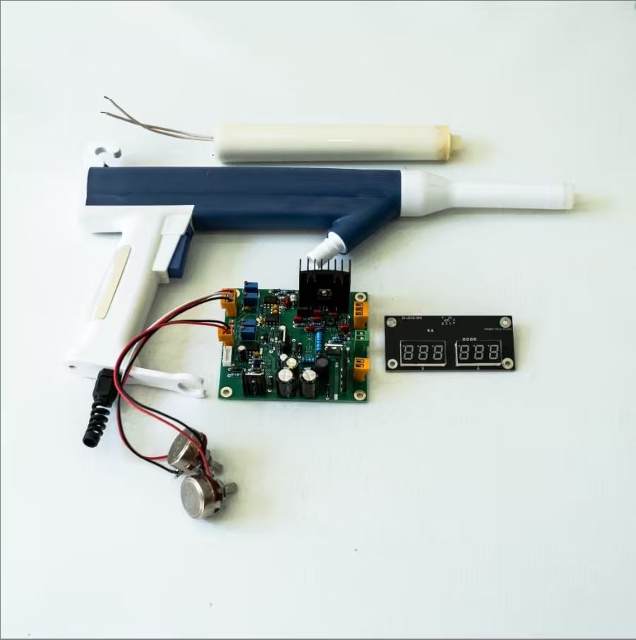
An ignition coil plays a central role wherever a system needs a brief, controlled high-voltage pulse from a lower-voltage electrical supply. Its job is not simply to raise voltage; it also stores energy temporarily and releases it at a useful moment. Understanding the ignition coil clarifies how high-voltage circuits create a spark or initiate another electrical discharge, and why correct coordination with switching and insulation matters.
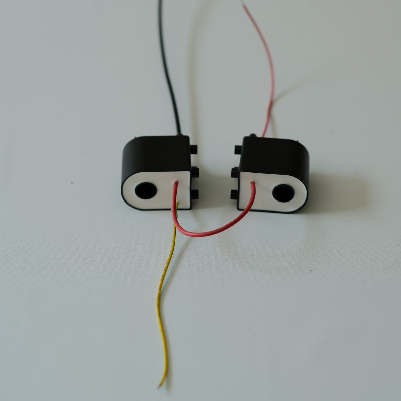
In practical terms, the ignition coil transforms electrical energy into a pulse suited to a high-voltage load, such as a spark gap. The ignition coil works as part of a circuit, so its output depends on the supply, switching device, winding design, and connected load. This article explains that role step by step, including what happens during operation and what engineers should consider when integrating the component.
How the ignition coil creates a high-voltage pulse
Energy storage in the primary winding
An ignition coil usually contains primary and secondary windings arranged around a magnetic core. When current flows through the primary winding, it builds a magnetic field and stores energy in that field. The ignition coil therefore acts first as an energy-storage element, not as a source that continuously supplies high voltage. The amount of stored energy depends on circuit conditions, including current, winding characteristics, and the time allowed for the field to build.
A switching device controls current through the primary side. While the switch is closed, the ignition coil develops its magnetic field; when the switch opens, primary current changes rapidly and the field begins to collapse. That change in magnetic flux is the key event that induces voltage in the secondary winding. The ignition coil must be matched to its driver, because timing and current control affect the energy available for each pulse.
Induction and voltage transformation
The secondary winding has many more turns than the primary winding in common step-up designs. As the magnetic field collapses, electromagnetic induction produces a voltage across both windings, with the secondary arrangement enabling a much higher output potential. The ignition coil thus converts a controlled change in primary current into a high-voltage pulse. The final voltage is influenced by winding design, circuit behavior, insulation, and the electrical load rather than by turns ratio alone.
A high voltage is useful only when the circuit can direct it to the intended point. In a spark application, the ignition coil output rises until the gap and surrounding conditions permit discharge. The pulse then creates a conductive path through the gap, allowing current to flow briefly. This means the ignition coil has a practical role in both generating voltage and enabling a specific electrical event, while the connected components determine how that event occurs.
How the coil supports reliable system operation
Coordinating pulse timing with the load
High-voltage performance depends on coordination between the ignition coil and the system controller. The switch must charge the primary winding for an appropriate interval, then interrupt current at the intended point in the operating cycle. If the timing is unsuitable, the ignition coil may not release energy when the load requires it. In equipment with repeating pulses, consistent control helps the circuit deliver predictable discharges across changing operating conditions.
The load also shapes the electrical response. A spark gap, electrode, or other high-voltage element presents a particular impedance and may behave differently as conditions change. The ignition coil should be evaluated with the actual load and wiring, not in isolation, because cable capacitance and connection geometry can influence pulse shape. Engineers use this system-level view to check whether the ignition coil and driver operate within their intended electrical limits.
Managing insulation and electrical stress
The high potential generated by an ignition coil places demands on insulation throughout the secondary circuit. Winding materials, spacing, terminals, connectors, and enclosure design all help keep voltage confined to its intended path. Dust, moisture, heat, vibration, or damaged insulation can create leakage paths or unwanted arcing. A design review should therefore consider the complete installation, including clearances and the environment around the ignition coil.
Switching also creates transient electrical stress, so circuit protection and component ratings matter. The ignition coil, driver, and associated wiring need to tolerate the voltage and current behavior expected during normal operation and foreseeable disturbances. Appropriate testing can reveal weak insulation, excessive heating, or unstable discharge behavior before deployment. These checks do not remove every risk, but they help verify that the ignition coil performs as intended within the assembled system.
Applying the role to design and maintenance decisions
Choosing a coil for the operating conditions
Selection starts with the required output behavior rather than a voltage figure alone. Engineers should define the load, pulse energy, repetition rate, supply range, switching method, and physical environment. The ignition coil must suit these requirements alongside its insulation and thermal limits. In some high-voltage applications, a dedicated transformer may be the better circuit element; the choice depends on whether the system needs controlled pulsed ignition or another form of voltage conversion. A suitable ignition coil reference can help clarify the distinction between component roles.
Mechanical integration deserves the same attention as electrical specifications. Mounting, lead routing, ventilation, and separation from sensitive electronics can affect reliability and electromagnetic interference. The ignition coil should be positioned so high-voltage conductors remain short and well supported where practical. Designers also need to confirm that service access does not expose technicians to stored charge or energized connections during inspection.
Diagnosing faults through system behavior
When a high-voltage circuit misfires or produces inconsistent output, the ignition coil is only one possible cause. Fault-finding should also examine the power supply, switching signal, grounding, connectors, insulation, and load condition. A weak or absent pulse may result from insufficient primary current, a control fault, or a breakdown in the secondary path. Checking the ignition coil as part of the full circuit avoids replacing a sound component while overlooking the actual failure.
Maintenance practices should reflect the equipment maker's procedures and the hazards of high voltage. Before inspection, technicians need to isolate power and follow appropriate discharge and verification steps. Visible cracking, contamination, loose terminals, unusual heating, or evidence of tracking can justify further testing. Recording operating conditions alongside symptoms helps identify patterns and determine whether the ignition coil, its driver, or the connected load requires attention.
FAQ
Does an ignition coil generate electricity?
An ignition coil does not create energy; it stores energy supplied by the circuit and transfers it through electromagnetic induction. The resulting high-voltage pulse depends on the supply, switching action, winding design, and load.
Why does an ignition coil need a switching device?
The switching device controls primary current and determines when the magnetic field builds and collapses. That controlled change allows the ignition coil to produce a pulse at the required time instead of delivering an uncontrolled output.
Can an ignition coil be used in every high-voltage system?
No. An ignition coil suits systems that need a pulsed high-voltage output, but other applications may require a different transformer or conversion method. Confirm load, duty cycle, insulation, and control requirements before selecting a component.