
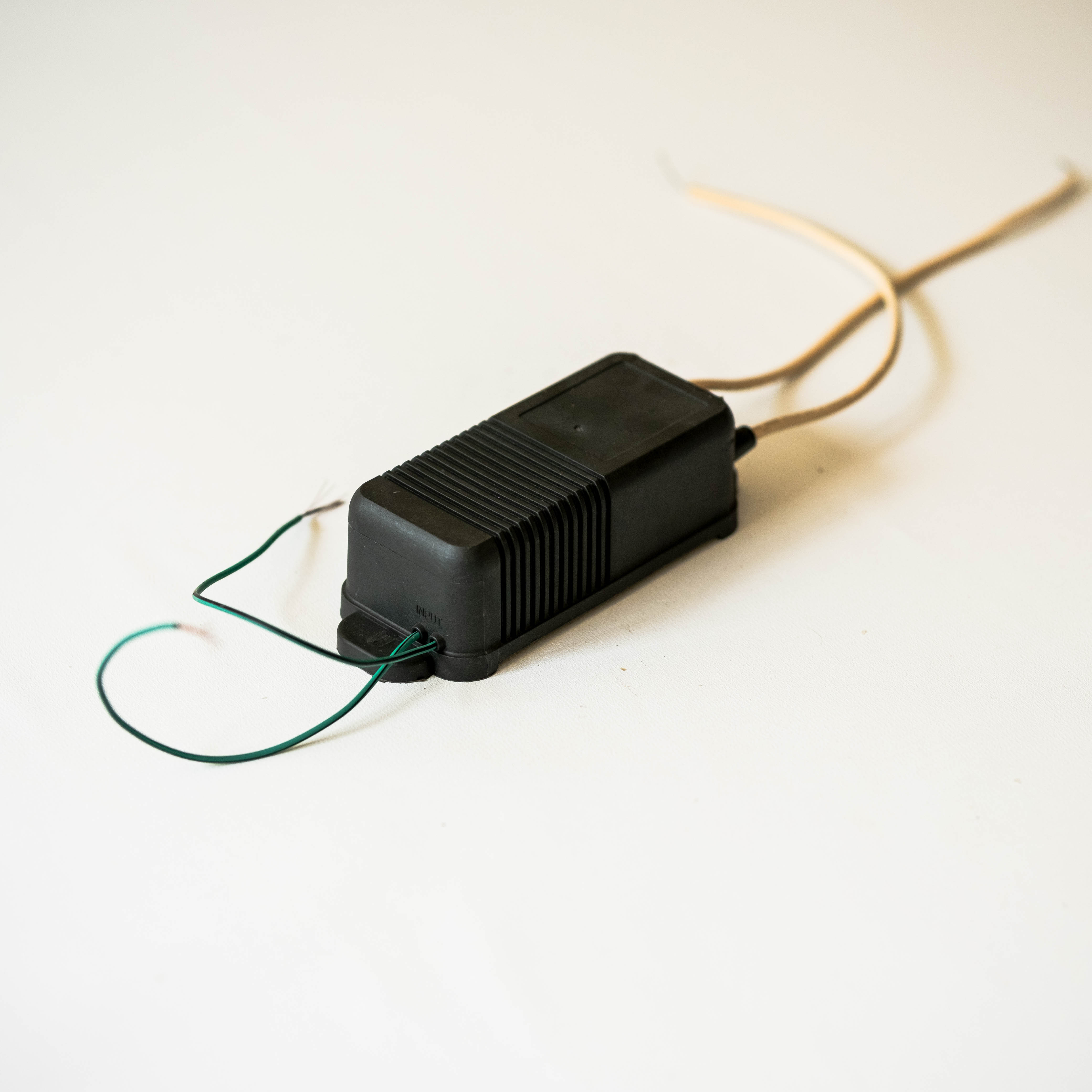
A flyback transformer in a high voltage system works by storing energy in its magnetic field during one part of a switching cycle, then transferring that energy to a load during another. This sequence lets a compact converter produce a higher voltage than its input. Understanding how a flyback transformer handles switching, isolation, and output control helps engineers assess whether the topology suits a particular power requirement.
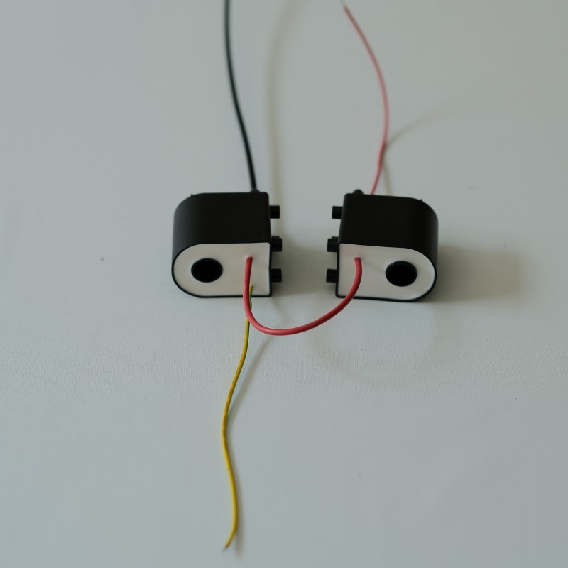
Unlike a conventional transformer that transfers power continuously between windings, a flyback transformer stores energy first and releases it later. That distinction defines the operating cycle, the required switching components, and the demands placed on insulation. In high voltage equipment, a flyback transformer must also manage electrical stress, output variation, and operating conditions while supporting the intended load.
The energy storage and transfer cycle
Switch on: building magnetic energy
A switching transistor connects the input supply to the primary winding of a flyback transformer. Current rises through the winding, creating magnetic flux in the core, and energy accumulates in the magnetic field rather than passing immediately to the output. During this interval, the secondary rectifier is reverse-biased, so the flyback transformer isolates the load from the primary energy-storage phase.
The rate at which primary current rises depends on input voltage, primary inductance, and the time the switch remains on. A controller sets this interval through its switching strategy, while current sensing can help limit stress on the transistor and magnetic components. Designers size the flyback transformer and its core for the energy required per cycle, avoiding saturation that could cause excessive current.
Switch off: delivering energy to the output
When the transistor switches off, the magnetic field in the flyback transformer collapses and winding polarity reverses. The secondary voltage then forward-biases its rectifier, allowing stored energy to flow into the output capacitor and load. The turns ratio contributes to the voltage conversion, but the flyback transformer does not alone determine the final output; switching conditions and feedback also matter.
The output capacitor smooths the pulsed energy into a more stable DC voltage between switching events. In many designs, the flyback transformer operates in discontinuous mode, where its stored energy is substantially released before the next cycle, or continuous mode, where some magnetic energy remains. The selected mode affects peak currents, control behavior, and component stress, so it should match the load and operating range.
How high voltage output is established and controlled
Turns ratio, rectification, and insulation
A higher secondary-to-primary turns ratio can help a flyback transformer generate a high secondary voltage from a lower input, but turns ratio is only one design factor. The winding arrangement, switching duty cycle, leakage inductance, and rectifier characteristics influence actual operation. Engineers evaluate these together because a high voltage converter must deliver useful output without exposing components to excessive voltage or current.
Insulation design is central when a flyback transformer serves high voltage equipment. Winding separation, insulation materials, clearances, and creepage paths must reflect the working voltage and applicable safety requirements. The construction also needs to account for local electric-field concentration, since sharp transitions and uneven winding geometry can increase stress. Good insulation planning supports isolation and helps reduce the risk of breakdown during intended operation.
Feedback and output regulation
A flyback transformer is part of a converter, not a standalone voltage regulator. A feedback circuit monitors an output condition and signals the controller to adjust switching behavior when load or input voltage changes. Depending on the design, regulation may use an isolated sensing path or a primary-side method. The control loop coordinates switch timing so the flyback transformer transfers enough energy to maintain the target output.
High voltage outputs can make measurement and feedback more demanding, so sensing components must be chosen for their voltage ratings and accuracy. Engineers also consider startup, short-circuit response, and the possibility of light-load operation. A flyback transformer designed around a single nominal point may not behave acceptably across the full input and load range. Testing those boundaries reveals whether the control approach is suitable.
Practical design and application considerations
Matching the converter to its operating conditions
To apply a flyback transformer effectively, first define the input range, required output voltage, load current, isolation needs, and operating environment. These conditions determine the energy required per cycle and inform choices for the core, winding ratio, switch, rectifier, and capacitor. A high voltage system with a changing load may place different demands on the flyback transformer than a system that runs at a steady operating point.
Thermal behavior and switching stress should be reviewed alongside electrical targets. Copper losses, core losses, leakage energy, and component heating can affect converter efficiency and reliability. Layout matters too: short switching paths and sensible separation between high voltage and low voltage areas can help manage noise and safety. If evaluating a specific flyback transformer, confirm that its documented ratings and construction align with the converter requirements.
Verification, limitations, and safe operation
A practical validation plan measures output regulation, ripple, startup response, and component temperatures under representative input and load conditions. Engineers should also inspect switching waveforms for voltage spikes and ringing that may arise from leakage inductance. Because the flyback transformer handles energy in pulses, probes and measurement procedures must be appropriate for the voltage levels and switching environment.
The topology has useful strengths, including a relatively straightforward way to provide isolation and multiple outputs, but it is not ideal for every power level or performance target. Peak currents and electromagnetic interference can become design concerns, especially as power demands rise. Selecting a flyback transformer therefore involves balancing size, control complexity, insulation, and thermal limits rather than focusing on output voltage alone.
FAQ
Why does a flyback transformer store energy instead of transferring it continuously?
A flyback transformer stores energy while the primary switch is on because the secondary rectifier is then reverse-biased. When the switch turns off, the magnetic field releases energy through the secondary winding to the output. This two-stage action is the defining operating principle and determines the converter’s current waveforms and component stresses.
Can a flyback transformer produce high voltage from a low voltage input?
Yes, a flyback transformer can support a high output voltage when the turns ratio, switching control, insulation system, and output rectification are designed for that purpose. The achievable output also depends on input range and load demand. Appropriate feedback and component ratings are necessary for controlled, safe operation.
What should engineers check when choosing a flyback transformer?
Engineers should compare the required input and output conditions with the transformer’s electrical ratings, insulation construction, thermal limits, and intended operating mode. They should also account for the controller, switch, rectifier, and feedback method, since these work together with the flyback transformer. Validation under realistic loads helps confirm the complete converter design.